kqcircuits.elements.waveguide_coplanar
- class kqcircuits.elements.waveguide_coplanar.WaveguideCoplanar[source]
Bases:
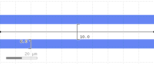
ElementThe PCell declaration for an arbitrary coplanar waveguide.
Coplanar waveguide defined by the width of the center conductor and gap. It can follow any segmented lines with predefined bending radios. It actually consists of straight and bent PCells. Termination lengths are lengths of extra ground gaps for opened transmission lines
The
pathparameter defines the waypoints of the waveguide. When a DPath is supplied, the waypoints can be edited in the KLayout GUI with the Partial tool. Alternatively, a list of DPoint can be supplied, in which case the guiding shape is not visible in the GUI. This is useful for code-generated (sub)cells where graphical editing is not possible or desired.Warning
Arbitrary angle bents can have very small gaps between bends and straight segments due to precision of arithmetic.
- static get_corner_data(point1, point2, point3, r)[source]
Returns data needed to create a curved waveguide at path corner.
- Parameters:
point1 – point before corner
point2 – corner point
point3 – point after corner
r – curve radius
- Returns:
A tuple (
v1,v2,alpha1,alpha2,corner_pos), wherev1: the vector (point2 - point1)v2: the vector (point3 - point2)alpha1: angle between v1 and positive x-axisalpha2: angle between v2 and positive x-axiscorner_pos: position where the curved waveguide should be placed
- static produce_end_termination(elem, point_1, point_2, term_len, face_index=0)[source]
Produces termination for a waveguide.
The termination consists of a rectangular polygon in the metal gap layer, and grid avoidance around it. One edge of the polygon is centered at point_2, and the polygon extends to length “term_len” in the direction of (point_2 - point_1).
- Parameters:
elem – Element from which the waveguide parameters for the termination are taken
point_1 – DPoint before point_2, used only to determine the direction
point_2 – DPoint after which termination is produced
term_len (double) – termination length, assumed positive
face_index (int) – face index of the face in elem where the termination is created
- static is_continuous(waveguide_cell, annotation_layer, tolerance)[source]
Returns true if the given waveguide is determined to be continuous, false otherwise.
The waveguide is considered continuous if the endpoints of its every segment (except first and last) are close enough to the endpoints of neighboring segments. The waveguide segments are not necessarily ordered correctly when iterating through the cells using begin_shapes_rec. This means we must compare the endpoints of each waveguide segment to the endpoints of all other waveguide segments.
- Parameters:
waveguide_cell – Cell of the waveguide.
annotation_layer – unsigned int representing the annotation layer
tolerance – maximum allowed distance between connected waveguide segments
path (Shape) - TLine, default=
(0,0;100,0) w=0 bx=0 ex=0 r=falseterm1 (Double) - Termination length start, default=
0, unit=μmterm2 (Double) - Termination length end, default=
0, unit=μmadd_metal (Boolean) - Add trace in base metal addition too, default=
Falseground_grid_in_trace (Boolean) - Add ground grid also to the waveguide, default=
False