Using waveguides
Coplanar waveguides are an essential element in many chips created with KQCircuits, acting as the wires that connect different elements together.
KQCircuits contains a powerful element WaveguideComposite, which enables drawing waveguides along a path of
nodes with many integrated features, such as adjustable-length meandering segments, in-line elements and changing
dimension or face. Other useful waveguide elements are SpiralResonatorPolygon
and WaveguideCoplanarSplitter.
This section shows how to edit waveguides in the KLayout GUI.
Modifying waveguides
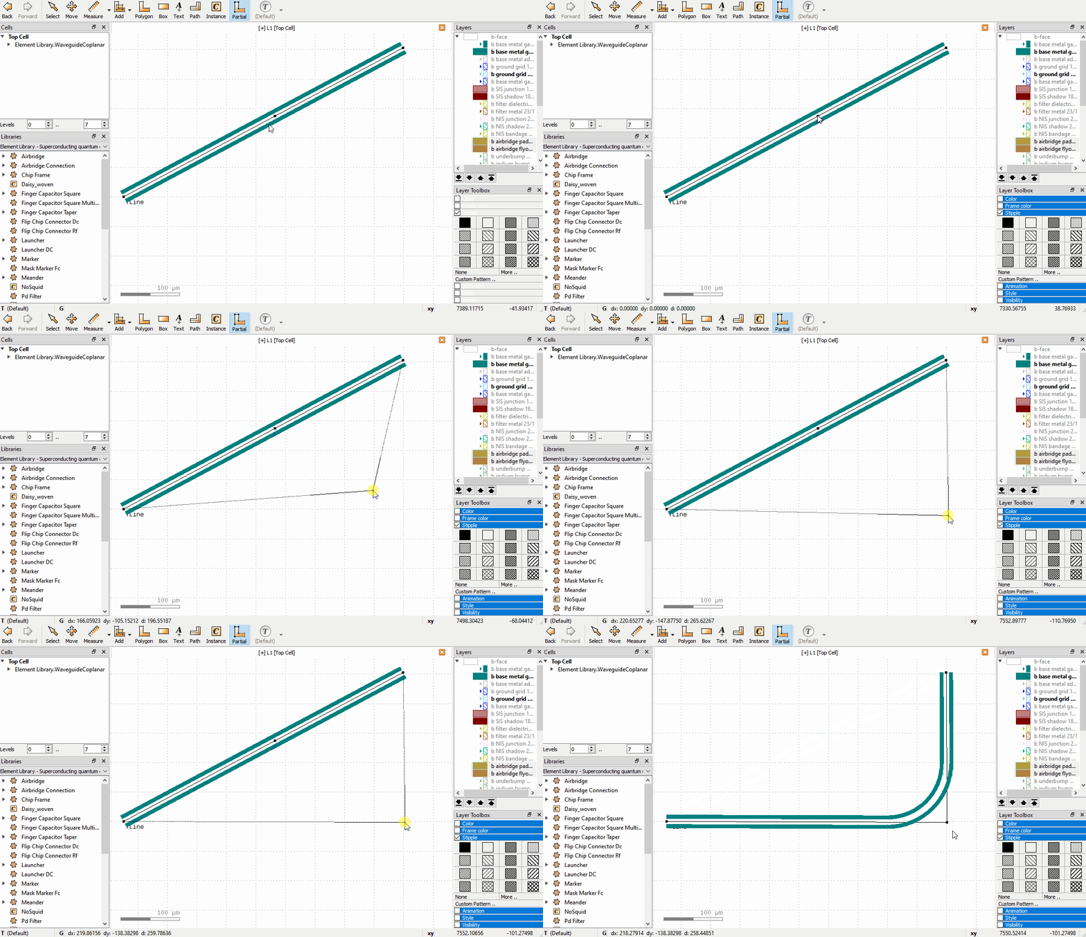
For some elements, the shape can be edited directly in the GUI. For example, Waveguide Coplanar,
Waveguide Composite and Spiral Resonator Polygon have paths that can be edited with the Partial tool.
The following operations are supported:
Drag a node to move it, or click to select, move, click to confirm.
Double click on an edge to create an additional node.
Click to select a node and press the
Delkey to delete a node.Drag edges to shift the edge; the neighboring nodes adjust to keep the path connected.
The following video shows these operations for a waveguide:

If the GUI paths are not visible, make sure that the option Show PCell guiding and error shapes is enabled under Display -> Cells in the KLayout setup.
Editing WaveguideComposite Nodes
Waveguide Composite is a very flexible element, that can be used to route complex waveguides. It can include other
elements that are automatically connected correctly inline with the waveguide, can insert meandering segments to
meet a specific waveguide length, and can include airbridge crossings or flip-chip connectors to route signals in a
3D integrated design.
A Waveguide Composite can be inserted like any other element, and the path it follows can be edited with the
Partial tool like other waveguides, as described above. However, to edit the advanced properties of each individual
Node, use the Edit Node tool in the toolbar.
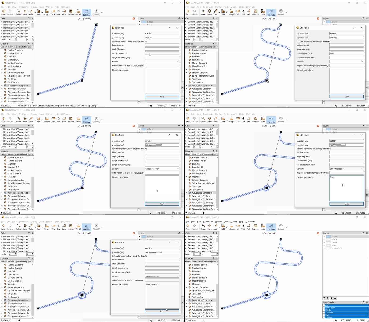
With Edit Node selected, click on any node to bring up the Edit Node dialog. The currently selected node is
highlighted by a dashed rectangle. Note that only waveguide nodes that are directly under the current top cell can be
edited, and only Waveguide Composite nodes.
In the Edit Node dialog box, the position, length, and other properties can be edited. Changes are updated when
Apply is clicked. If an inline element is chosen, the element’s properties can be entered as key=value pairs, each
on a separate line. See the API documentation for the PCell parameters supported by each element.
The following video shows the workflow with the Edit Node tool:
