kqcircuits.elements.chip_frame
- class kqcircuits.elements.chip_frame.ChipFrame[source]
Bases:
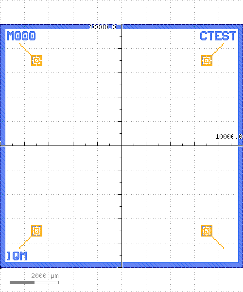
ElementThe PCell declaration for a chip frame.
The chip frame consists of a dicing edge, and labels and markers in the corners.
box (Shape) - Bounding box of the chip frame, default=
(0,0;10000,10000)dice_width (Double) - Dicing width, default=
200, unit=μmdice_grid_margin (Double) - Margin of the ground grid avoidance layer for dicing edge, default=
100name_mask (String) - Name of the mask, default=
M000name_chip (String) - Name of the chip, default=
CTestname_copy (String) - Name of the copy, default=
Nonename_brand (String) - Name of the brand, default=
IQMframe_text_size (Double) - Label text size, default=
350, unit=µmtext_margin (Double) - Margin of the ground grid avoidance layer around the text, default=
100marker_dist (Double) - Distance of markers from closest edges of the chip face, default=
1500diagonal_squares (Int) - Number of diagonal squares for the markers, default=
10marker_types (List) - Marker type for each chip corner, clockwise starting from lower left, default=
['Marker Standard', 'Marker Standard', 'Marker Standard', 'Marker Standard']chip_dicing_width (Double) - Width of the chip dicing reference line, default=
10.0, unit=µmchip_dicing_line_length (Double) - Length of the chip dicing reference line, default=
100.0, unit=µmchip_dicing_gap_length (Double) - Gap between two chip dicing reference dashes, default=
50.0, unit=µmchip_dicing_in_base_metal (Boolean) - Insert chip dicing lines in base metal addition, default=
Falseface_label_show (Boolean) - Show face label below variant label, default=
Trueface_label_size (Double) - Vertical size of character in face label, default=
75, unit=µmface_label_margin (Double) - Margin of the ground grid avoidance layer around the text in face label, default=
50face_label_x (Double) - X offset of face label, from top right corner of chip, default=
100, unit=µmface_label_y (Double) - Y offset of face label, from top right corner of chip, default=
450, unit=µm