Getting started
Here, we will show an example how to create your own elements.
Each element must be placed in a new python file in the directory corresponding to the correct library, for example
the Elements library contains files in the kqcircuits/elements folder, and the Chips library corresponds to
the kqcircuits/chips folder..
If you have installed KQCircuits as a salt package, make sure to create a user package directory, see
Setting up a user package directory. Your custom elements are then placed in the corresponding subfolder, for example
my_package/elements and my_package/chips.
You can use the KLayout built-in Macro Editor (press F5, and look under Python, [Local - python branch]), or use an external editor or IDE to create and modify the files.
For more details on the file structure, see General Structure and Miscellaneous Utilities.
Defining a custom element
Each element must be placed in a new python file in the directory corresponding to the correct library, and inside the file a single class is defined.
For example, to create an element called My Element, right click the elements directory in the macro editor
and click New. Choose Plain python file, and name it my_element. In the new file, place the definition of
the MyElement class.
Note
The python file name and element class name should match. In the file name, use lower case and underscore to separate words. In the class name, use a capital letter for each first letter of a word.
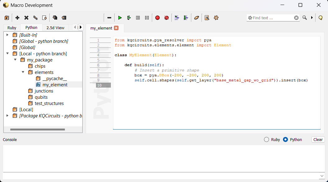
The following code is an example element definition:

In the code above, we define the MyElement class with a single method build. Inside the build method, we
define any code needed to draw the geometry. In this example, a square (box) is placed in the base_metal_gap_wo_grid
layer.
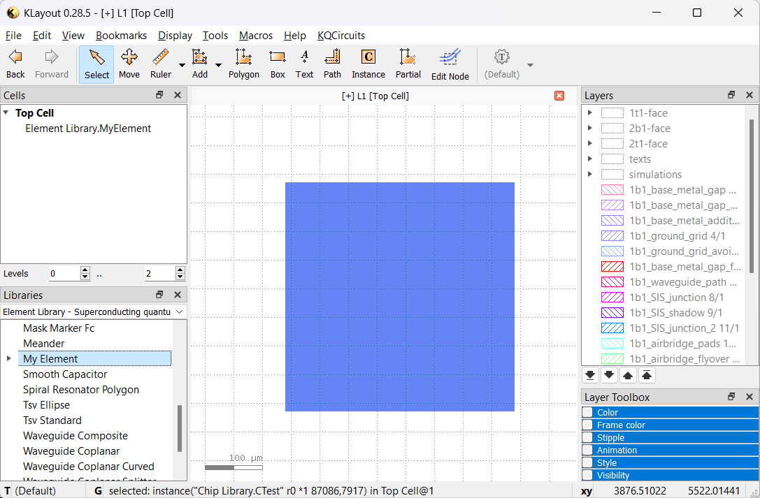
After editing the code, save the changes (Ctrl+S), and in the KLayout main window choose the
KQCircuits -> Reload libraries menu item. Now, the element will appear in the Elements library, and you can
place it by dragging and dropping to the drawing canvas. As usual, after placing the element press * and F2 to
make sure everything is visible.

Note
Each time you make changes to an element in the Macro Editor, you must Reload libraries for the changes to appear. If there are errors in the code, you may get an error message while reloading.
Defining a custom chip
Next, we will define a custom chip that uses our new element. The process is the same as with elements, just create
the file in the chips directory.
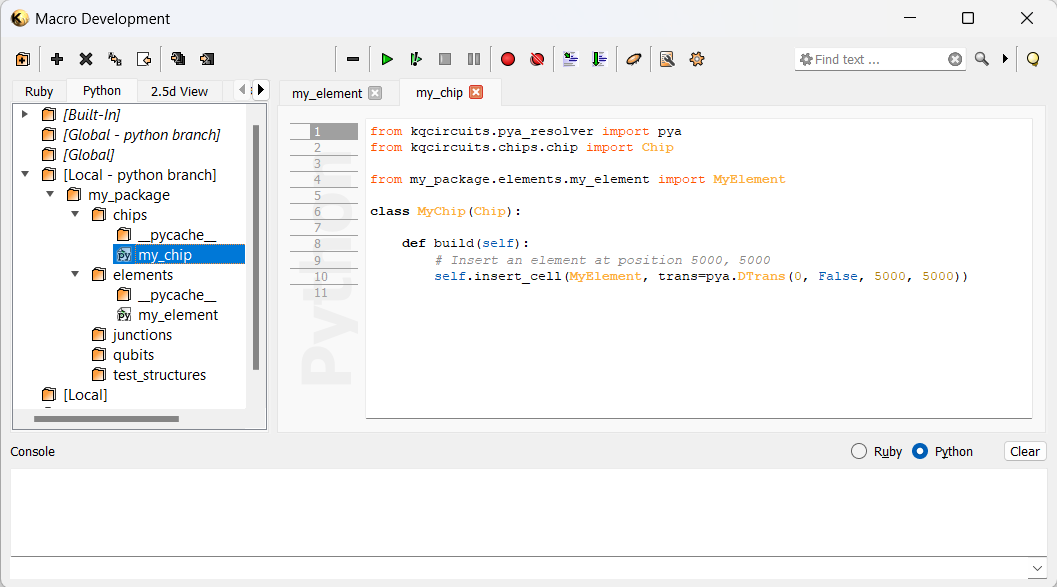
Here is an example to create a chip:

Note, that for standard KQC elements we use the import statement from kqcircuits.elements..., but for our custom elements
we import it from our user package, in this case from my_package.elements....
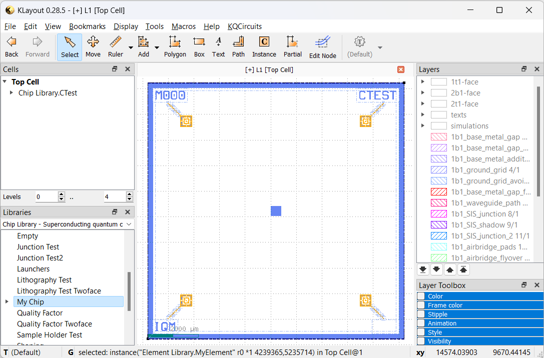
After saving the chip and reloading libraries, the new chip appears in the Chips library:

For more information on coding elements and chips, see Structure of Element code. Also see the API documentation for details on the built-in elements and chips available in KQCircuits.